Powering Holiday Lights with YouTube Videos
The title of this article has less to do with SEO optimization and more with the fact that, yes, I will actually be showing you how to make holiday lights dance to YouTube content. Let’s also dig into why this is important and how the craft can be applied beyond the home and into retail and enterprise environments.

Theater and Musical Lawns
The Internet of Things (IoT) is literally everywhere. Banks, hospitals, manufacturing, civil engineering, and so on. Did you know that IoT applications also extend to parades and even the theater? The Curious Incident of the Dog in the Nighttime is perhaps the best example of a theater production using IoT as one of the main mechanics throughout the entire show–So much so that at the end of the production they even itemize part numbers and the various systems behind the effects. At home, coordinated holiday displays usually go viral once per year. There’s likely an example set up in your neighborhood this year. Most of them consist of a holiday song that can be heard from a speaker on the lawn or by tuning a car radio to an advertised station to provide musical rhythm to the synchronized light show. I’ll go into detail on how these setups work in an upcoming article, but for now I would like to focus on one of the easiest ways to get a coordinated effect that is scalable and extremely budget friendly!
The Hardware / Software
There are, of course, hundreds of ways to build a captivating holiday light show or display. Some methods may utilize simple switches and timers while others may use powerful processors and physical logic boards. The goal in this article is to keep the hardware and software requirements to a minimum, so to accomplish this we will be using three simple components:
- Jinx – (Software — $0)
- Wemos D1 ESP8266 – (Wifi Chip/Controller — $2)
- WS2811/WS2812B LED Lights – (String Lights — $13-22)
Edge vs Centralized Processing
Before I continue, I would like to note that there are two main ways lights are controlled under the tiny ESP8266 chips and each method is equally as important to consider depending on your application.
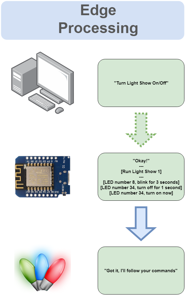
- Edge Processing
- Edge processing simply means that the lights are controlled by instructions hosted on the physical chip. Typically this means each chip has a number of pre-configured light chases/sequences and then a computer connected to the network then tells the chip which sequence to queue up. In other words, the computer is only telling the chip a very basic on/off style command. This method also typically suggests that the chip itself hosts a little web server to control and select which sequence or effect to run.
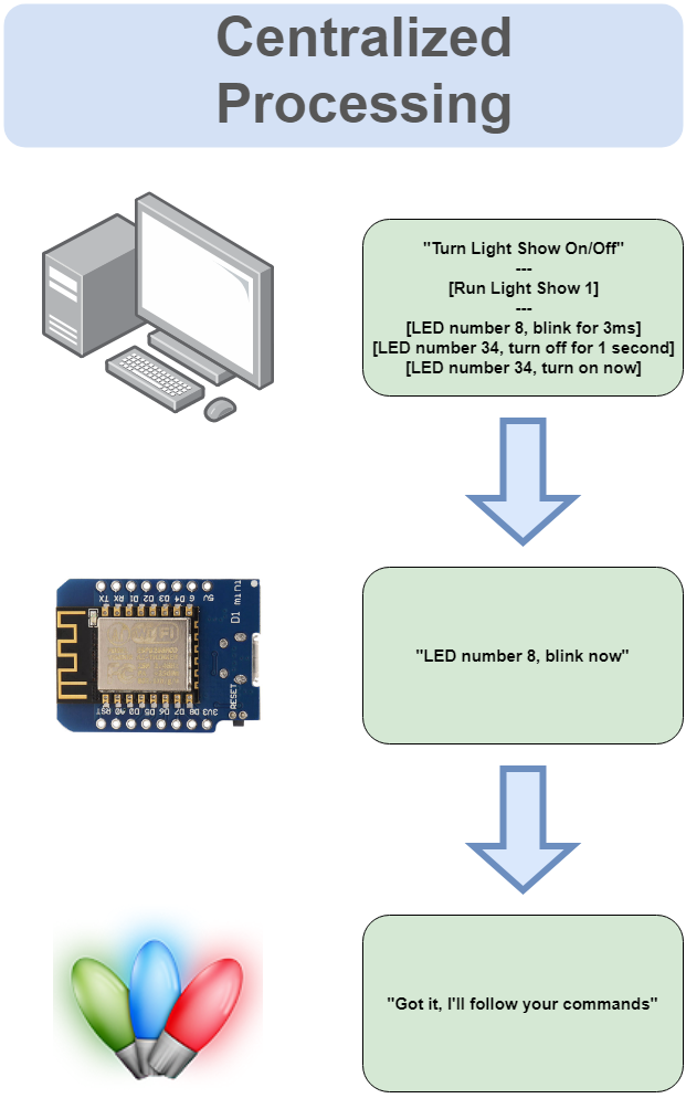
- Centralized Processing
- Centralized processing involves the use of a computer that uses each chip as a sort of messaging conduit so that each LED light is can be individually controlled from a central source. In other words, the chip is only programmed to be a lightweight instrument that connects to a network and has no ability to produce any effects or control any LED lights by itself. The chip simply listens for instructions from a computer.
The benefit of using an edge processed chip is that a complicated network is not required. The chip simply powers up and can run a beautiful and exciting display based on what has been pre-configured. If network connectivity is disrupted, the lights will still carry on with their programmed sequence.
The benefit of using a centralized form of processing is that the LEDs are not limited to a set of pre-configured sequences. Software that exists outside of the chip allows for a broader and more dynamic/interactive use as well as the ability to control many chips at once. This method also allows software to include microphones, cameras, and touch controllers to modify the patterns and visual dynamics of a display. (Or, perhaps YouTube videos!) If, network connectivity is lost, however, the display will immediately stop. For that reason it is important to again consider both methods.
A Quick Note About Art-Net
Art-Net is a widely used common protocol (language) used by most of the world’s concert stage lighting/designing experts. Because of its wide use, this means it can be used to send instruction messages to a wide array of devices light strobe lights, fog machines, disco balls, and practically every form of light and laser on a stage. Using this protocol also allows for a wider range of software choices that can all seamlessly communicate to devices. All of this combined means we theoretically could put a Christmas tree on stage and have each light coordinate with everything else in its immediate vicinity using the centralized computing approach.
Let’s begin!
The ESP8266 Chip
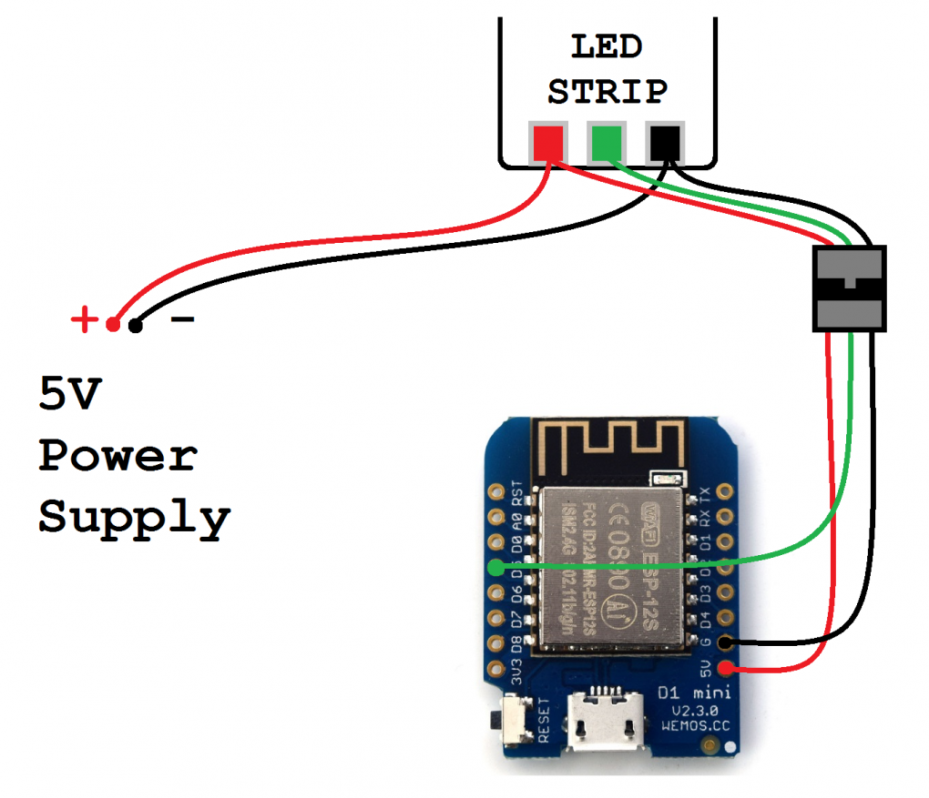
I will start off with how to prepare the Wemos D1 ESP8266 chip hardware and software. Most strands of WS2811 and WS2812b LED lights will start with a 3 Pin JST connector for easy connectivity. Solder the three source pin connector wires to the Wemos D1 board. Positive (+) Red, Negative (-) Black, and Data (D) which is typically Green. The Data wire can be soldered to D5.
The Wemos D1 chip works really well as an Art-Net node, or client. Art-Net can be installed on a chip using the Arduino Sketch program and this [amazingly simple] code provided by RStephan
The code requires just a couple of modifications before uploading.
// Wifi settings
const char* ssid = "ssid";
const char* password = "pAsSwOrD";

// LED settings
const int numLeds = 8; // CHANGE FOR YOUR SETUP
const int numberOfChannels = numLeds * 3; // Total number of channels you want to receive (1 led = 3 channels)
const byte dataPin = 2;
CRGB leds[numLeds];- Wi-Fi credentials (SSID, Password)
- “numLeds” — How many individual LED lights are you trying to control on the strip this specific chip will be connected to
- “dataPin” — What pin did you solder the Data wire to (D5)
The Software
The software we will use is called Jinx and fully supports Art-Net. The main reason Jinx exists is to combine LED lights into one giant screen. If you’ve ever had the chance to get up close to a mega screen at a sports stadium or a display at a high-end retail/fashion spot, you’ll see the screen is actually composed of individual LED lights that output a significant amount of light when consolidated in a matrix/grid layout. Jinx is able to control each of those LED lights and assign them a brightness and hue to represent a photo, effect, or video.
Jinx is fairly easy to operate once everything has been configured. The initial setup procedure involves three main parts:
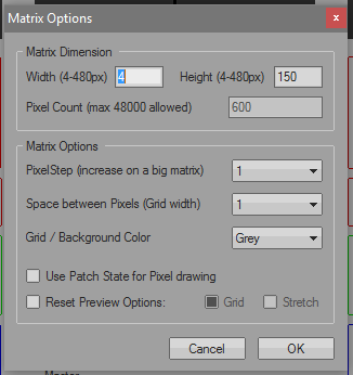
1.) Set up the matrix — A “matrix” in this context refers to the size and shape of the screen, or output. If you cut the length of light strips to include 50 LEDs each and run 30 of them side by side, this would result in a 50×30, or 30×50 matrix (depending on the orientation of the screen). For the purpose of the Christmas tree example, the light string is one long vertical and linear array of lights, so the matrix would be 1 by however many LEDs have been connected. For my example, I have 150 LED lights in the string, so my matrix is ideally 1×150 or 150×1. Jinx unfortunately has a minimum requirement for matrix size, so the lowest pixel count on either X or Y is 4. Therefore, the array in my example is actually a width of 4 and a height of 150.
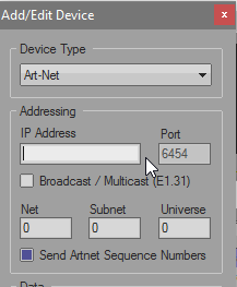
2.) Add output devices — Next we have to define where the signal output is sent to. The Wemos D1 ESP8266 chip that was programmed to accept Art-Net is exact that. Manually enter the IP address of the Wemos D1 chip and leave everything else default unless any other configurations were modified, such as the universe ID.
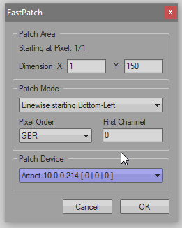
3.) Define the output patch — So far we have the matrix screen set up to accommodate all 150 LED lights and Jinx is now aware of the Wemos D1 chip’s existence. The only thing left for setup is to tell Jinx where, on the matrix, the chip (and associated LED lights) should sit on the matrix. The Fast Patch feature allows you to quickly add each individual LED address to the matrix in just a few clicks. There is an option to define the RGB order according to the lights, which may need to be modified to GRB if using the WS2811 string lights. Not changing this will result in red output showing up as green and vice versa.
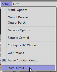
Once all three sections have been configured, it is just a matter of choosing “Start Output” in the Setup menu. From there, every option in the main interface exists to customize a visual display. Scenes, automations, and custom effects can be loaded into each of the four effect channels and mixed to combine each effect using the fade sliders.
YouTube videos, in my example, can be included in the effects by either screen capturing a full screen playlist or downloading the videos and playing them in the included AVI player effect.

Jinx has the ability to output to many devices at once, and each output can reflect specific areas of the matrix relative to their physical positions. For example, I could have multiple decorations around the house displaying and coordinating content with the Christmas tree.

Thinking beyond the holidays, this setup is a massively powerful tool when considering interactivity in retail, trade show displays, and other commercial and enterprise applications. Retailing consultants are always on the lookout for new and exciting ways to engage an audience and captivate attention. LED lights have long been instrumental in this process and until now have been generally passive as it relates to engagement. With Wi-Fi based control and intelligence behind the sensors, LED driven displays have the potential to instantly attract an audience. It’s not a matter of whether or not this application will ever see massive popularity and deployment, but when.